This is a discontinued product, a newer model is available:


Rotortuner RT-2000
Please note that the Rotortuner RT-2000 is now obsolete and has been replaced by the RT-6 System.
Comprehensive Rotor Track and Balance (RTB) solutions, unique advanced vibration analysis capabilities, and user-friendly interface make the RT-2000 the engineer's favourite RTB equipment.
Description
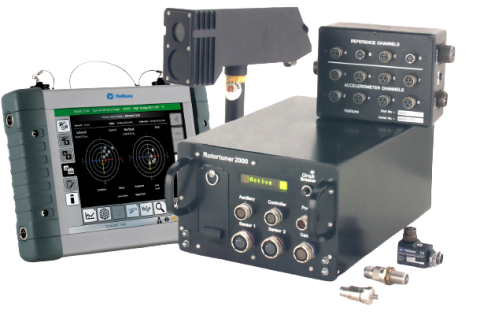
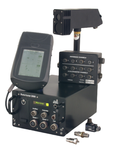
Fully compliant with the appropriate sections of Mil.Std.810E, DIN 40 050 IP44, and RTCA DO-160C, the Rotortuner 2000 (RT-2000) is a portable or semi-permanently installed Rotor Track & Balance (RTB) and vibration analysis system for use on helicopters and fixed-wing turboprop aircraft.
System control
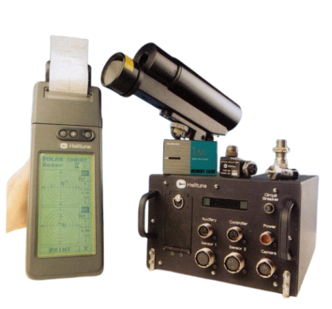
Overall control of the RT-2000 is through an ergonomically designed hand-held terminal with a touch-sensitive membrane over a high-resolution backlit LCD display. Robust and easily readable it’s ideally suited to the demands of the flight deck or cockpit environment and is powered by the Data Collection Unit. All data and solutions may be viewed in flight and hard copies obtained from the integral printer. The unit currently supports three user-selectable languages: English, French and German.
Aircraft data cards
The RT-2000 is configured for use with different target machines by the use of Data Cards. These cards contain all information necessary for the RT-2000 to collect data and to offer the correct options for rotor track and balance solutions.
Track data analysis
The rotor track data may be collected automatically with the balance data or can be viewed in real-time for the fault diagnosis of blade lead/lag and /or pitch change mechanism problems. Individual blade positions may be retained on-screen to build up a composite picture of blade movement for the duration of the viewing period. A variety of other views are available for data review and track diagnosis.

Balance data
Balance data is displayed on the hand-held terminal the moment data collection is complete. The data is also stored on the PCMCIA test card for immediate review and diagnosis. The data can be displayed against any adjustment type as polar diagrams or in text formats. The solution algorithm is fully configurable and allows the operator to choose from the available adjustment types, flight conditions and axes for inclusion in the solution.
Data input and storage
Data from the proven Line-Scan Camera, 8 or 16 accelerometers, and 4 or 8 tachometer channels are integrated into the Data Collection Unit to provide data viewable as polar balance plots, vibration signatures and rotor track height and lead/lag displays. All data is stored to a removable data transfer medium for data transfer and subsequent detailed offline analysis in the Ground Support Station.
Vibration data
RT-2000 offers a unique vibration data collection and analysis feature. Small ‘Windowed’ frequency ranges (not starting at 0Hz) can be configured from within the 30KHz frequency range. When displayed with up to 6400 lines, a very high resolution can be obtained. This facility enables the operator to extract and highlight frequencies of special interest for specific aircraft diagnostic requirements such as gearbox or engine diagnosis.

Vibration absorbers
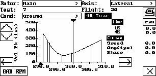
Many aircraft types incorporate vibration dampers which require tuning to be most effective at reducing vibration, at the blade passing frequency, and at the standard operating speed of the rotor. An easy-to-use vibration absorber set-up program is included as part of the RT-2000 Firmware to assist in the tuning of these absorbers. Data is collected from the aircraft and displayed on the NR tune graph, the system then performs the necessary transfer function calculations to determine the actual tune status compared with the target status. From this, the operator can easily identify if the absorbers are operating at the correct frequency, and if not he can identify the correct remedial action.
Firmware upgrade options
The system is designed so that future improvements and upgrades to the overall system functionality, as well as refinements to aircraft information, may be incorporated through the use of Firmware Upgrade Cards or Aircraft Data Cards supplied on PC cards.
Product Specification
| Performance Data | |
| Sensor Inputs | Up to 16 accelerometers, 8 reference,1 tracker. |
| Frequency Range | Up to 30kHz in windowed ranges set to suit specific aircraft and operator requirements. |
| FFT Analysis | Up to 6400 lines resolution |
| Electrical Specification | |
| Connectors | MIL C 38999 Series III 21 –32V DC at 4 Amp maximum. Protected against over-voltage, reverse polarity and power loss. |
| Power Supply | Max. power consumption 100W |
| Physical Specification | |
| Data Collection Unit | |
| Dimensions | 150 mm x 230 mm x 320 mm (361mm with front and rear handles) |
| Weight | 5.8 Kg |
| Operating Temperature | -20 to +55 degrees Celsius |
| Hand Held Terminal | |
| Dimensions | 70 mm x 147 mm x 273 mm |
| Weight | 1.25 Kg |
| Operating Temperature | -20 to +55 degrees Celsius |
| Data Collection Accuracy | |
| Vibration | +/- 0.2% of scale range |


